Diploma project


ENSA Paris Malaquais
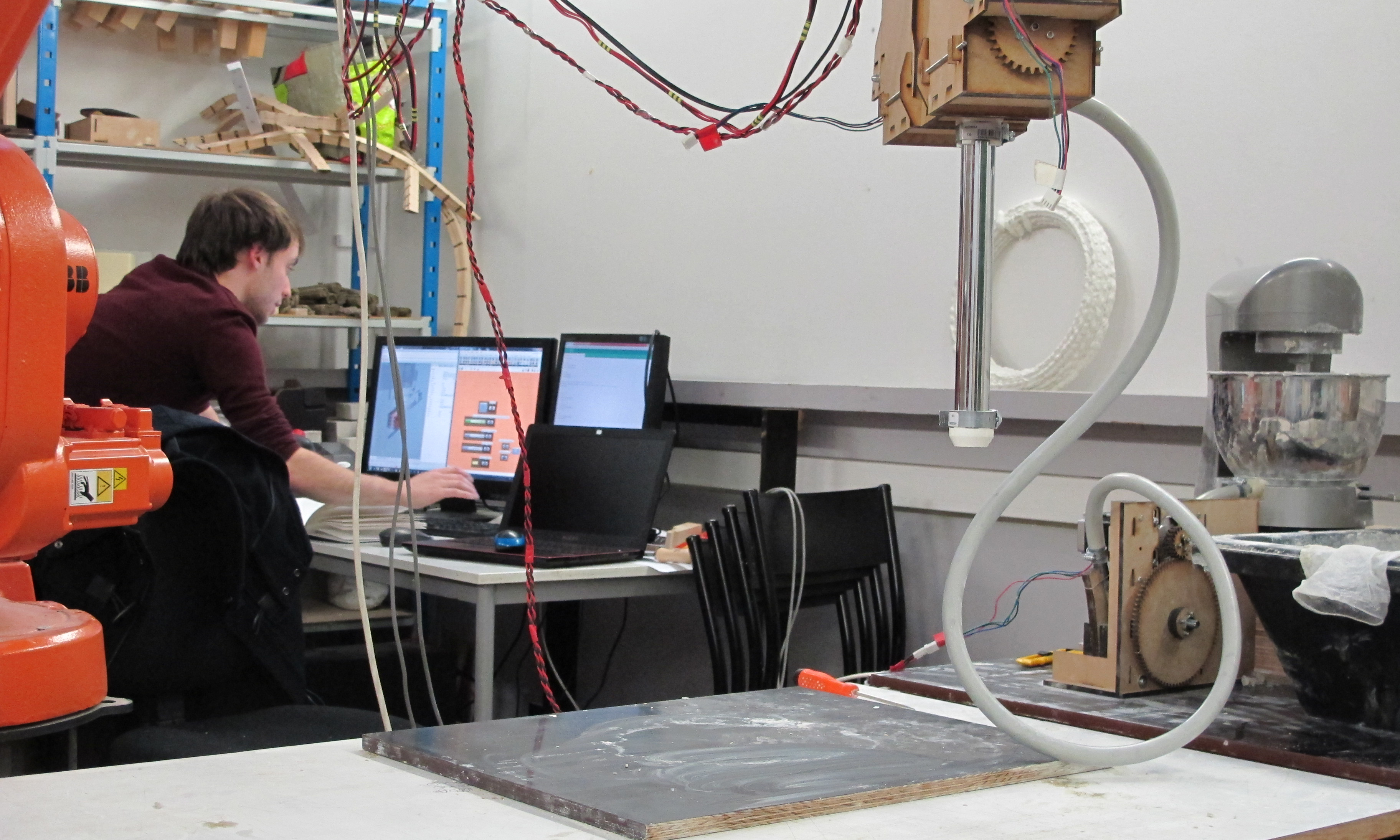
I worked for three years on an experimental research project about large scale additive manufacturing of cimentitious graded material from design to manufacture. I began to work on this subject during my first master term. It became gradually a team project. I led the research all along my master. During my final project I continued to work on this subject in the framework of a research project funded with the DEMOCRIT symposium with as partnership the ENSAPM, the ENSAM, the PIM, Hal Robotics and LafargeHolcime. This work led to several articles : Additive manufacturing and multi-objective optimization of graded polystyrene aggregate concrete structures , Design Modeling Symposium, Springer, 2015 and Large-scale 3D printing of ultra-high performance concrete - a new processing route for architects and builders Material and design 2016. The last one came out of the research project founded by the DEMOCRITE symposium.
Additive manufacturing technologies are today an important topic in the scientific field. Any kind of material can be printed (ceramic, metal, polymer, even organic cells). However, most of the technologies are made to manufacture small or medium scale object. Today there are no fully fonctionnal additive manufacturing technologies to build an architectural scale object. Few research about large scale additive manufacturing are being developed sine the end of the 20st century. The most interesting of them are D-shape and Contour Crafting. Since the first building prototypes were made in 2015 by the WinSun company in China lot of research program on this subject have been created.
Most of the researches on additive manufacturing are focused on fabrication technologies. There are even a few research investigations about developing large scale specific designing methods to generate advance geometry that takes into account the manufacturing constraints. Indeed, we can't use computer aided drawing software to design 3D printed projects. We need to use computer aided design software to use all the potential of this manufacturing process. The material feature and the manufacturing constraints entail non-standard and complex shapes that can't be drawn in computer aided drawing software. With computer aided design softwares we can create a project in relation with constraints by using the simulation tools.
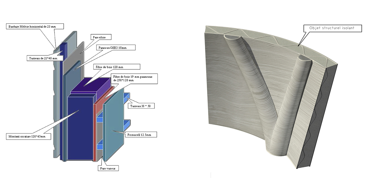
Additive manufacturing redefines the boundaries of the architectural elements. With this manufacturing process, there is no need to to divide the building in layers in relation to the specialist worker succession (structural wall, insolating material, facade). A synergy can be created between the different building organs that could create a new architectural element topology. Thus, this manufacturing process entails an integrative approach of the knowledge used during the design of the architectural project.
This work is about « design to manufacture » adapted to architectural scale additive manufacturing throughout a cross-disciplinary approach. The objective was to design, optimised and manufacture architectural element prototypes in relation to architectural design, technical performances and manufacturing process. Generate an optimised geometry for additive manufacturing is a complex work because the performances of a 3D printed object depend on 3 scale levels : the material properties, the tool-path deposition and the global morphology. Each one of them needs to be optimised in relation with the others.
I studied several aspects of this topic: the additive manufacturing process, the material formulation, the mechanical properties, the tool-path strategies and the morphology optimisation. I will now introduce briefly each one of those subjects.
About the additive manufacturing process. There is for now no industrial operational turnkey solution. That is why I worked on a specific selective deposition manufacturing process. Indeed, that type of additive manufacturing process is more efficient for large scale object than selective solidification process. It was adapted to cementicious material. This process was thought to achieve graded performance material printing from structural to insolated material.
This process consists of two steps. First a mortar premix is prepared with reological behavior appropriate for pumping. At this stage the material has a small granulometry distribution, a low plastic yield value, a long setting time and be the less thixotrop as possible.
Then this premix is pumped to a printing head were several additives are added to the mixture to increase the plastic yield value, reduce the setting time and increase the thixotropie material properties. Otherwise, other specific additives can be added to change the material performance. In this work some tests were made with light aggregates (polystyrene beads) to change the material performance from structural to insulated material.
About the material formulation. I successively work with two different companies about the material formulation. I first worked with Chryso during the first three master's terms (it was a non formal collaboration). Then, with Lafarge/Holcime in the framework of the research project funded with the DEMOCRIT symposium. For this research project LafargeHolcim developed a formulation adapted to additive manufacturing. The formulation derived from ultra high performance concrete (UHPC) (even if depending on the very small granulometry, this must be defined as a mortar). Therefore, it contains silica fume, a very low E/C (<0,1). Otherwise, it is optimised for the manufacturing process described above.. It has a long workability time and is composed of a specific polymer-base resin to reduce the structural interface issues between layers.
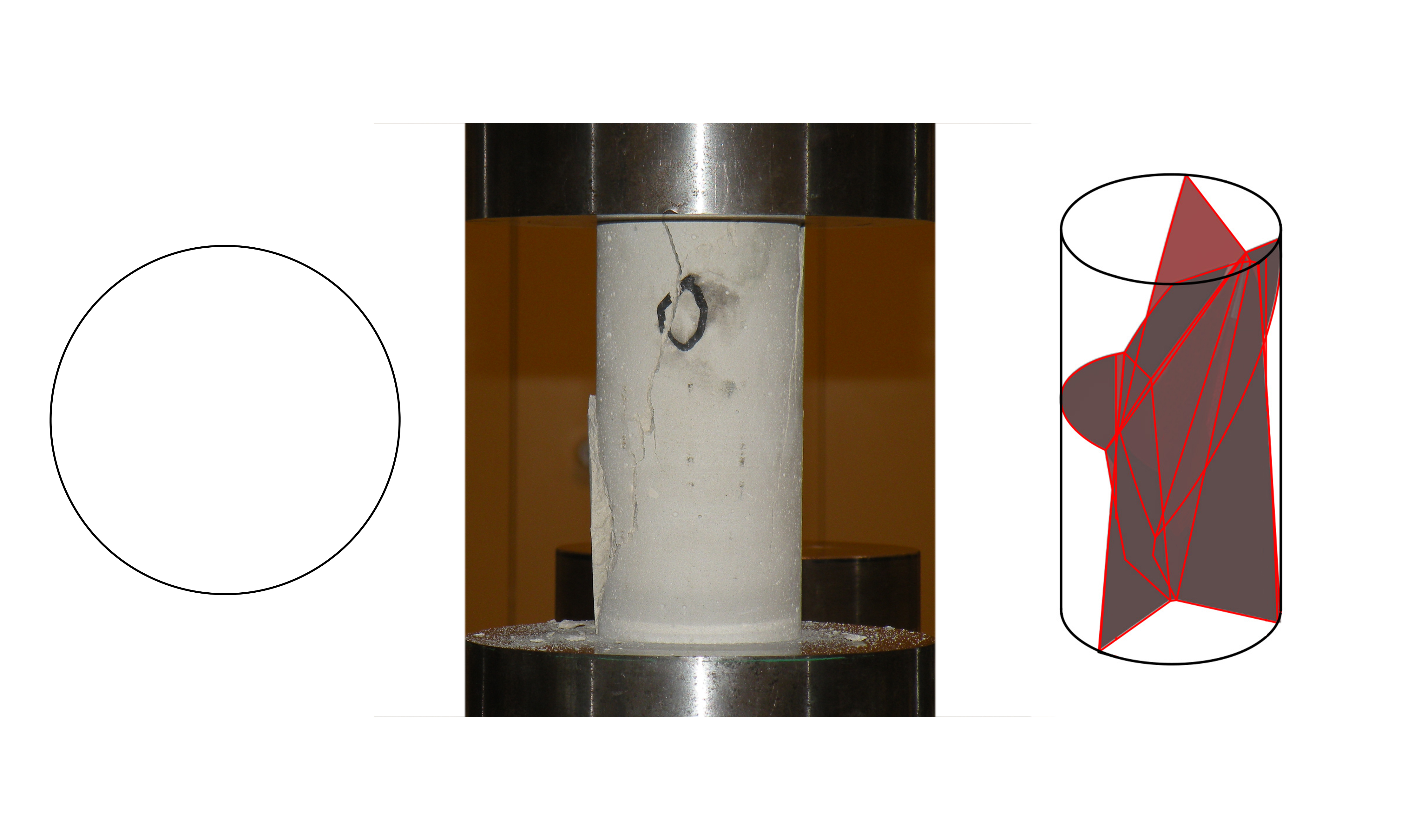
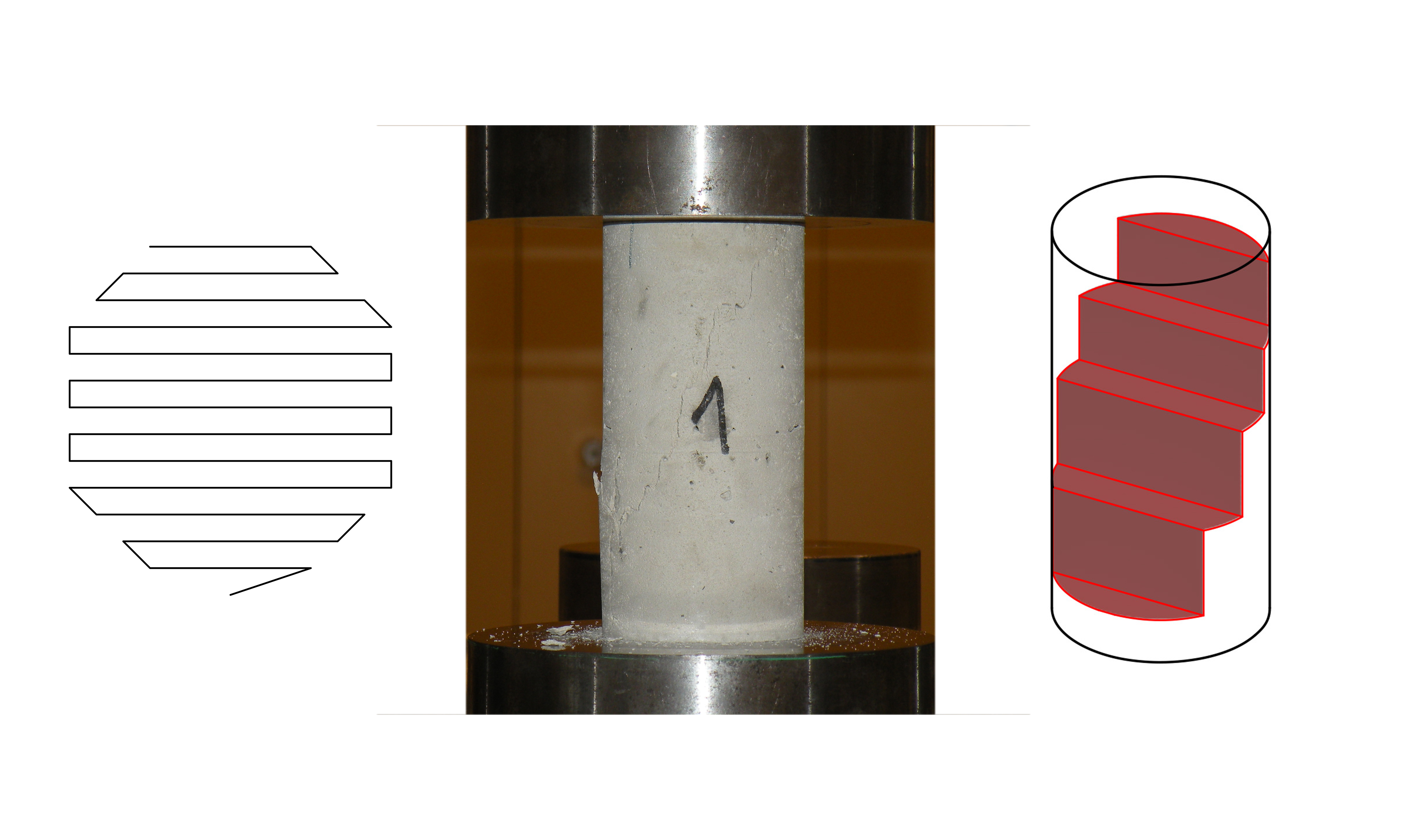
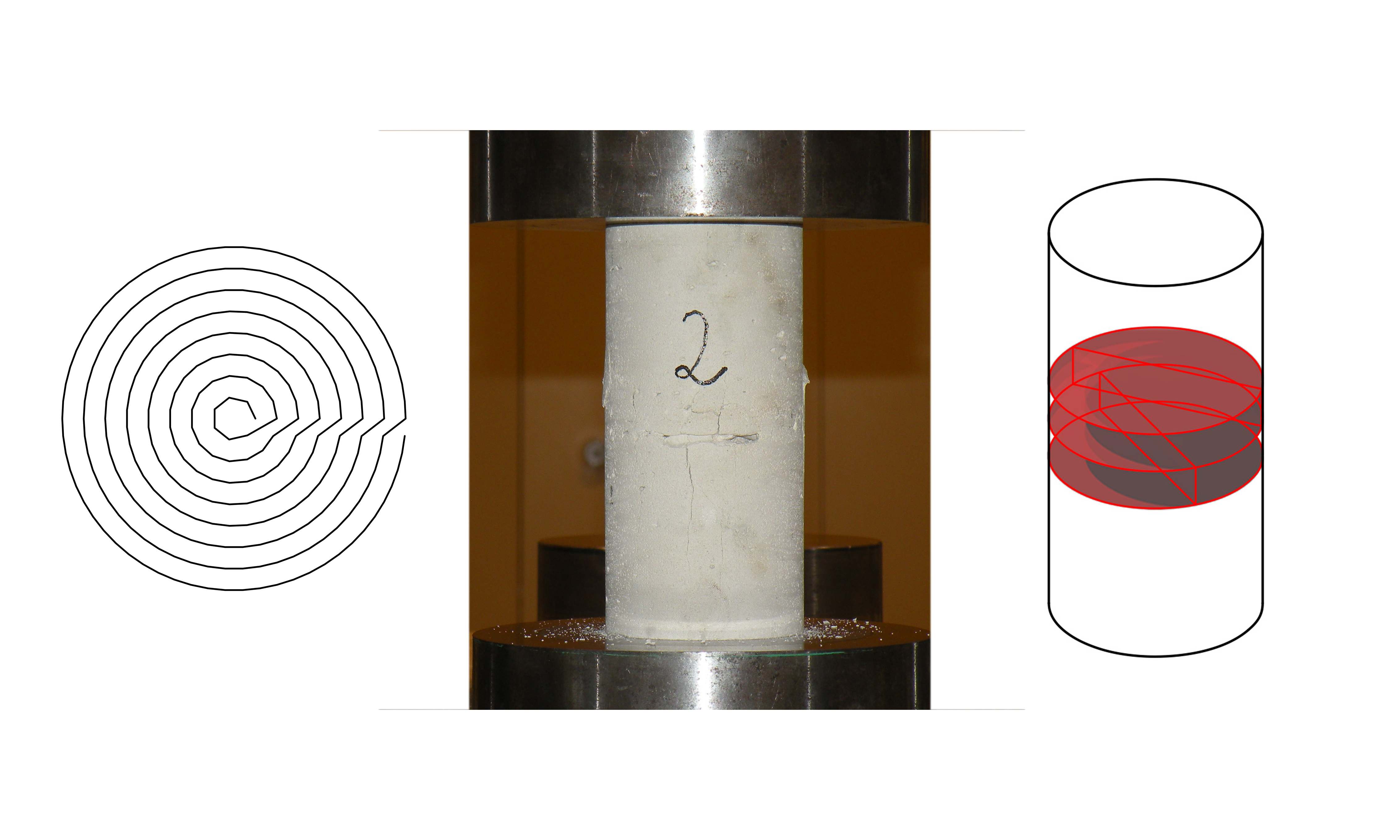
About the mechanical properties. Two specimens series were tested. The first serie was made with Chryso material for my master thesis. It was a compression test on cylindrical specimen. This test was made to compare poured mortar against printed mortar and also to determine the relation between the the tool-path and the material performance and fracture feature. The compressive resistance of printed specimen is roughly 40% less important than the poured specimen one and the fracture failure is directly linked to the tool-path. Printed mortar has a pseudo ductile failure method (it is not brittle as the poured mortar). The second test serie was made with lafargeholcime material. It was a flexion test to compare poured mortar against printed mortar. There was only 10% difference between the structural performances of the two groups of samples .
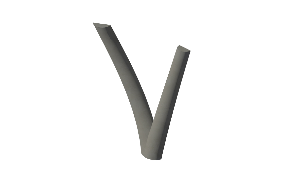
About the tool-path strategies. The classical slicer software we can use for polymer 3D printing are not adapted to large scale objects. Indeed, those slicing methods consist of planar layers constituted of one or several boundary laces and a filling lace pattern. Otherwise, because we are dealing with planar layers the objects produce with this method can be compared to corbel structures, which is one of the less efficient structure typology because it make the laces work with flexion and, in some case, the interfaces work with traction. To create a tool-path method adapted to large scale object we have to orient the laces in the three dimensions. This can be done by using the layering anisotropy to optimise the behavior of printed structure. The layer interfaces are the week structural point. The best orientation for those interfaces is to constrain them in compression. However the laces work fine with traction, especially if we are dealing with a fiber-reinforced mateial. To design an object that takes into account those constraints, we needed to generate a 3D tool-path which is totally different than classical planar layering methods.
About the morphology optimisations. I worked with two engineers on a GA-based multi objective optimisation algorithm. It was designed to optimised the repartition of several materials depending on their properties. Basically, we were working on an algorithm that can optimise the distribution of structural and insulated material depending on the specific boundary constraint (thermal and load constraints). This algorithm was not taking additive manufacturing constraints into account.
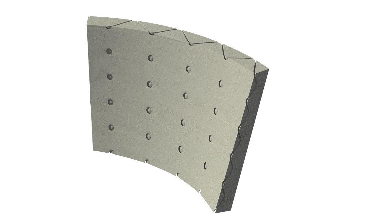
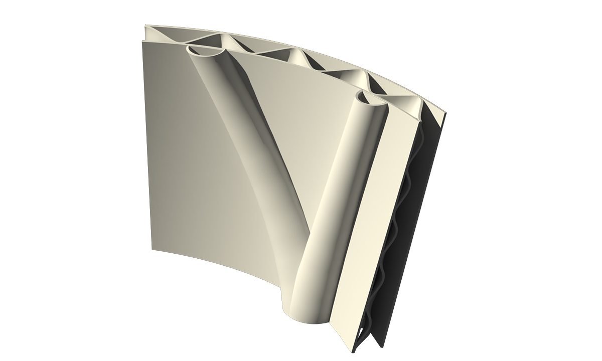
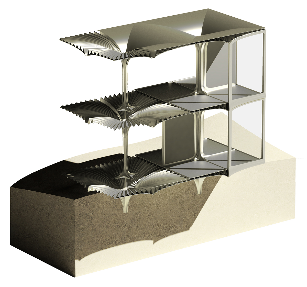
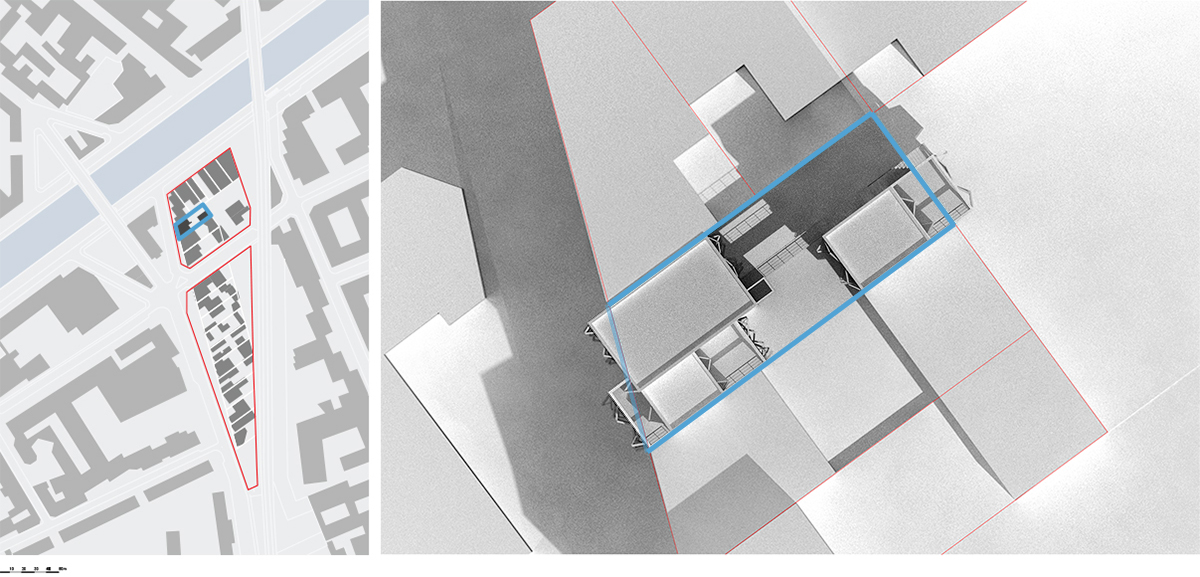
During my last term project, we chose to work on a case study of a reconstruction project where the existing structure is extremely damaged. The reason of this choice was to work with a contrained environment. Indeed, that kind of existing environment is a huge constraint that requires complex non-standard architectural éléments. The idea was to design a project made to be built with large scale additive manufacturing of cementitious material and produces a scale 1:1 architectural element. This design project took into account all the research introduced above about the manufacturing process, the material formulation, the mechanical properties, the tool-path 3D strategies and the morphology optimisation.
The architectural element produce was a loosed formwork. It is constituted of two parts : one made to receive poured structural mortar and one made to received poured insulated mortar. The structural part is designed in relation to a specific load. The insulated part is designed to reduce thermal bridges. The tool-path is generated to orient the lace interfaces perpendicular to the compression stress.
Master thesis
Master thesis
ENSA Paris Malaquais, France
Master 2 | 1st term
Teacher : Robert Le Roy
Student : Clément Gosselin
My master thesis also focused on large scale additive manufacturing process of cementitious material. This was a scientific work that contains a series of research and experiment about that focused on cementitious material adapted to additive manufacturing process. The following thematics were approached: cementitious material formulation, rheological characterization, mechanical evolution across time of young age cementitious material, mechanical performance characterization.
Thus, compression mechanical tests were realized on cylindrical specimen to characterize two things: the different about mechanical performance between poured and printed mortar and the impact of the toolpath, whether the laces orienta-tion, on the mechanical performances and the fracture method of printed objects. The experiment consisted of realized three cylindrical specimens made to be tested in compression. One poured mortar specimen and two printed mortar specimens, each of them with a different toolpath. One was realized with an orthogonal toolpath and the other with a concentric one.
A part of this work was published in the article Additive manufacturing and multi-objective optimization of graded polystyrene aggregate concrete structures, Design Modeling Symposium, springer 2015.
Multi material large scale additive manufacturing


P9
ENSA Paris Malaquais
Masteur 2 semestre 1
Enseignant : Philippe Morel, Jean Aimé Shu
Etudiant : Romain Duballet, Clément Gosselin et Philippe Roux
Ce travail porte sur la fabrication additive grande échelle multi matière. Contrairement à mon travail de mémoire, celui-ci s'intéresse davantage aux méthodes de conception ainsi que les scénarios constructifs adaptés à ce procédé de fabrication. Effectivement, ce procédé de fabrication permet de réaliser d'un seul tenant des objets intégrés comprenant différentes fonctions telles que structurelles et isolantes thermiquement ou encore acoustiquement. Ainsi, les méthodes de dessin assisté par ordinateur (DAO) ne sont pas adaptées pour concevoir des objets destinés à être imprimés. Pour utiliser tout le potentiel de ce procédé de fabrication il faut développer des outils d'aide à la conception.
Ainsi, nous avons travaillé sur des méthodes d'aide à la conception en développant un algorithme génétique permettant de réaliser des optimisations multicritères. Cet algorithme fut mis au point sur le logiciel Mathématica. Le but de celui-ci était de nous permettre de générer des éléments architecturaux répondant à un cahier des charges spécifique comprenant différents critères de performance tel que des performances mécaniques, thermique ou encore acoustique. Concrètement nous nous sommes intéressé au cas particulier d'un élément architectural ayant des propriétés à la fois structurelles et thermiques. Tout l'enjeu était de définir correctement le problème de l'optimisation multicritère pour que l'algorithme converge vers un optimum qui soit un compromis entre chacune des deux performances.
Une partie de ce travail a été publié dans l’article Additive manufacturing and multi-objective optimization of graded polystyrene aggregate concrete structures, Design Modeling Symposium, springer 2015.
Multi material additive manufacturing


P7
ENSA Paris Malaquais
Masteur 1 semestre 1
Enseignant : Philippe Morel
Etudiant : Clément Gosselin, Mahriz Akavan
Au cours de ce semestre nous nous sommes intéressés au applications dans le secteur de l'architecture de la fabrication additive multi matériaux. Il existe quelques exemples de méthodes d’impression 3D multi matériaux cependant, Il s’agit de méthode d’impression pour de petit modèles. L’intérêt de ce type de technique est de pouvoir s’affranchir des méthodes de coffrage usuelles ainsi que de pouvoir intégrer dans un seul objet différents éléments et matériaux qui, avec des technique de fabrication traditionnel, auraient été réalisé en plusieurs parties. Ainsi, la fabrication additive permet des réaliser des objets complexe possédant différents matériaux en un seul bloque. L’assemblage est donc remis en question par le procédé de fabrication car il est possible de s’en affranchir partiellement. Ce qui nous intéresse dans les impressions 3D multi matériaux, c’est la possibilité de contrôler point par point les performances du matériau mis en œuvre.
Le projet consiste en une recherche expérimentale sur l'utilisation de l'impression 3D multi-materiaux en architecture. Pour ce faire nous avons simplifié le problème en nous focalisant sur une seule variation de performance. Nous avons opté pour faire varier la densité dans le but de faire varier les performances du matériau imprimé de structurel, pour des densités élevées, à isolant pour des densité faibles. Les variation de densité étant, pour la réalisation de prototypes, obtenues par ajout de bille de polystyrène dans une matrice cimentaire. Ce matériaux nous permettaient d'obtenir des densité allant de 0,3 à 2,2. Nous avons travaillé sur des méthodes d'aide à la conception pour répartir les gradient de densité dans un volume de matière. Ici, nous avons opter pour des attracteurs de forte ou de faible densité.
Regressive resolution


Regressive resolution
ENSA Paris Malaquais
Licence 3 | 2nd term
Teacher : Pierre Cutellic
Student : Clément Gosselin, Charles Bouyssous
This project studio was an introduction to computationnal architecture by practicing simulation and programing. This studio included some programming courses on processing software.
We worked on a desert landskape. Those landskape contain profusion of a specific material like sand, ice, salt or sulphure. The idea was to simulate the formation of prearchitectural shapes by changing environemental parameter (température, pressure...) at two différent scales (a small and a global one).
Hence we studies deserts to see what kind of chimical reaction can be done in those environement depending on the local material. We focuce on chimical reaction that prodious solids. We get intereste in brine cristalisation. Hence, we situate our project on ice floe
We studied the bine cristalisation to identify all the variables involved in this changing state to realise a digital model that can simulate the cristalisation agregates. The variables involved in this reaction was the température the pressure and the salt concentration. The digital model was operationg at two différent scale (micro and macro).
Machine vision


Machine vision
ENSA Paris Malaquais
Licence 3 semestre 2
Enseignant : Félix Agid
Encadrant : Tristant Gobin
Etudiant : Clément Gosselin, Paul Poinet, Mathieux Venot
The workshop goal was to create an expérimental protocol that generates an architectural design thought the analyse of the intrinsic data of a territory by using industrial machine vision tools (Robotrealm). This workshop containe introduction lectures about machine vision. We studied basic picture algorithm applied to robotic.
Our work was about the automation of picture interpretation. We first create a collection of 50 discrete pictures that follows rigorous drawing rules. Those rules were about colors (green, red and blue), drawing shapes (dots, single line, polyline, curves...) and tool thickness. Each of those drawings were then processed through an algorithm as a territory map at three different scales : the landscape, the city and the building.
Generative Manufacturing


Generative Manufacturing
Echange Carleton university, Ottawa
Licence 2 semestre 1
Enseignant : Johan Voordouw
Etudiant : Ryan Fogarty, Clément Gosselin, Hanson Mak, Ekaterina Tchoupriko
This was a two week workshop. The aim was to design and fabricate a furniture scale project by using parametric tools with a high intrication level. The design was realise with Rhino and Grasshopper software. The main difficulty was to realise a unique assembly that can be used to connect all the panels no matter the variation of the relative angle between the panels.
Research center


P5 : Research center
Echange Carleton university, Ottawa
Licence 3 semestre 1
Enseignant : Inderbear Riard
Etudiant : Clément Gosselin
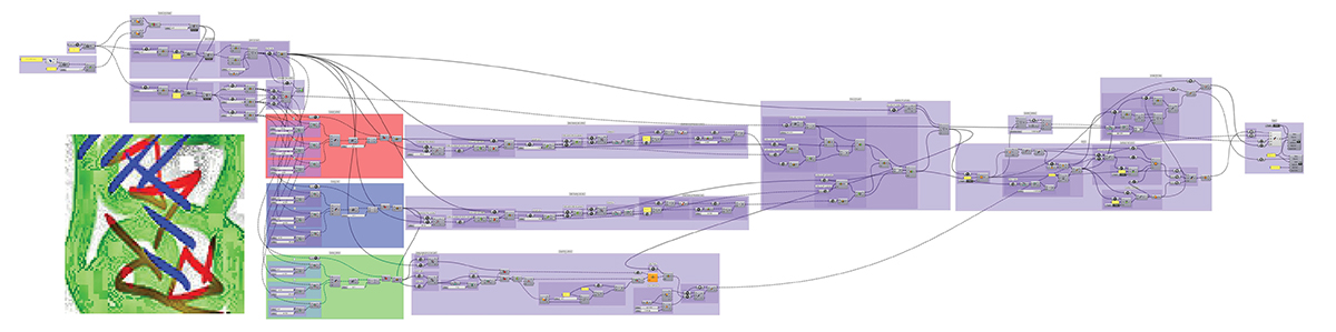
This is an experimental project that was entirely design with parametric software. The design is the result of the definition of mathematics Boolean rules. Those rules make an algorithm which is defined with a programming language. The architecture is generated by this algorithm. There are three main definitions in the project: the space, the program and the structure.
_The space is discretizes by a 3D regular grid of points which are the potential position of voxels (space unite).
_Each part of the program is defined by a gathering of voxel that follow repartition rules depending on the type of the space.
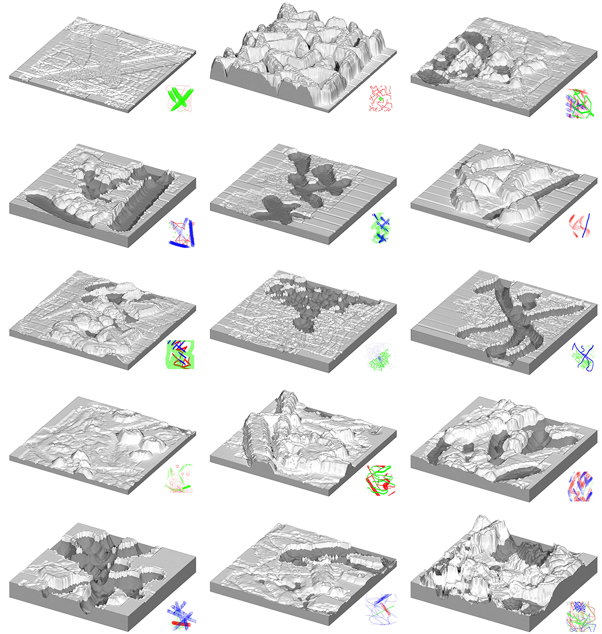
_The structure is intricate to the space unite repartition: it is composed by parametric modules. They follow functions that optimized the shape of the structure depending on the position of the spaces unites.
Hence those rules, the building can evolve and growing up according to the needs. Because the building shape is complex the entire building could be 3D print with robot including in its design (the building could be built by itself). To make the building evolve, you just defined the space unit you want to add, then the software adjusts the structure to build it, and then robots actualized the structure by 3D print the new space.
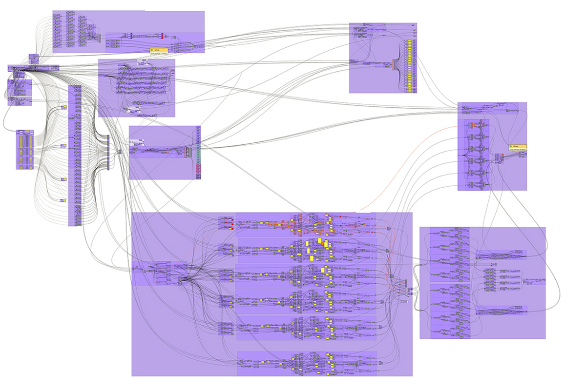
Screen shot du grasshopper définissant le projet.
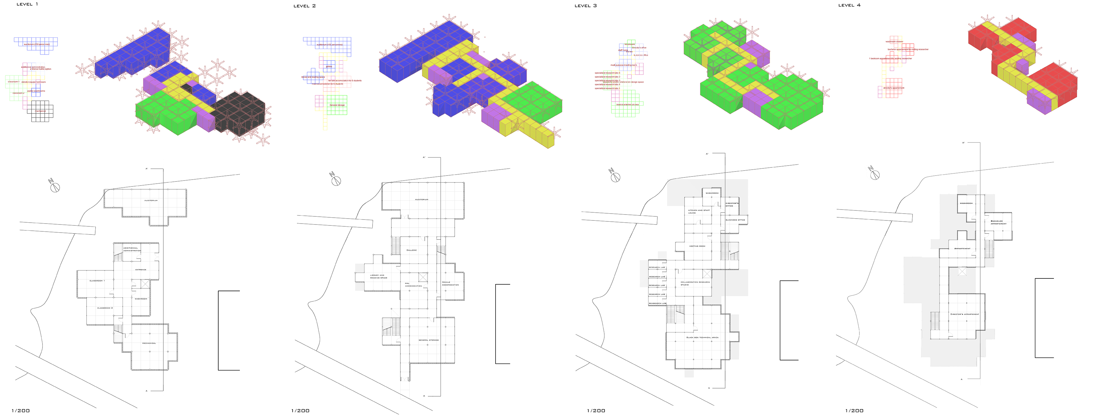
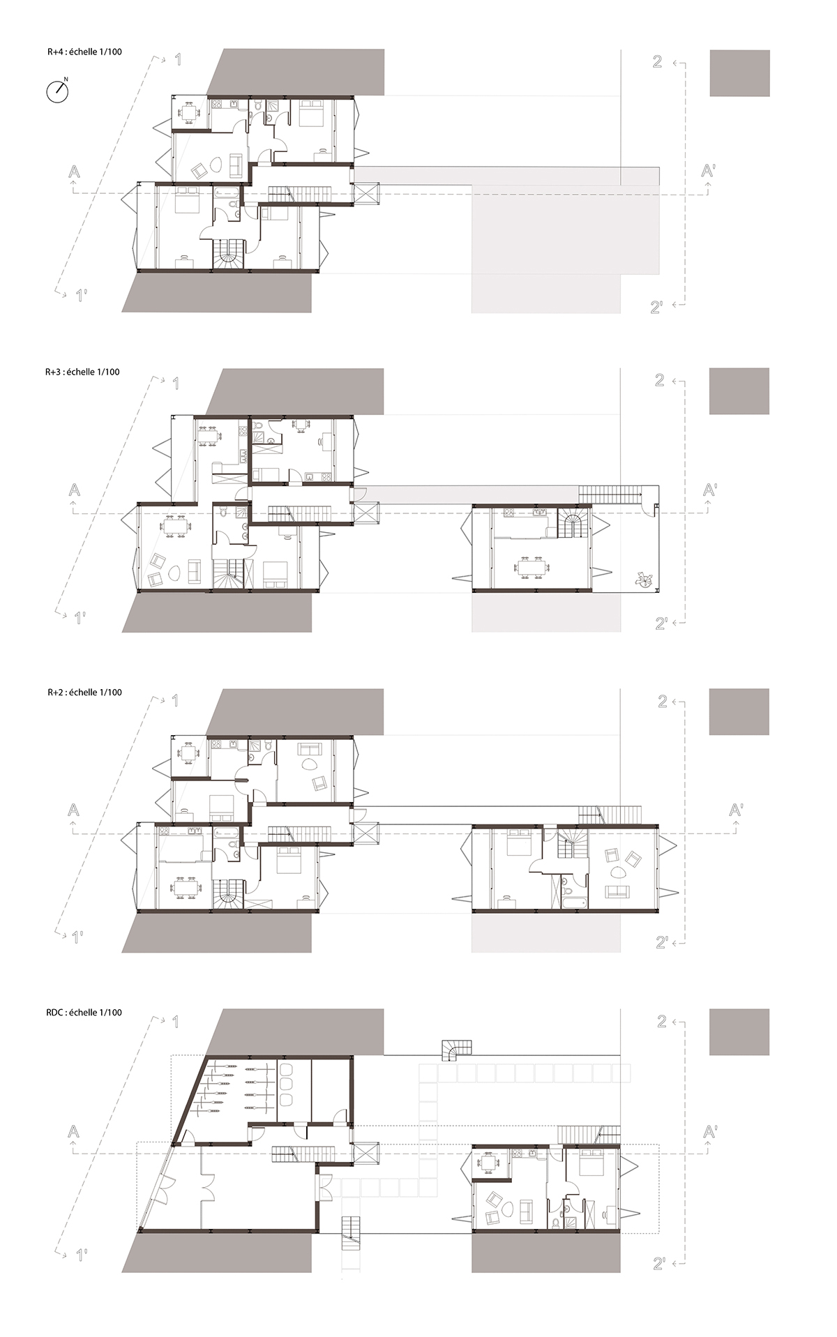
Plans d'étages
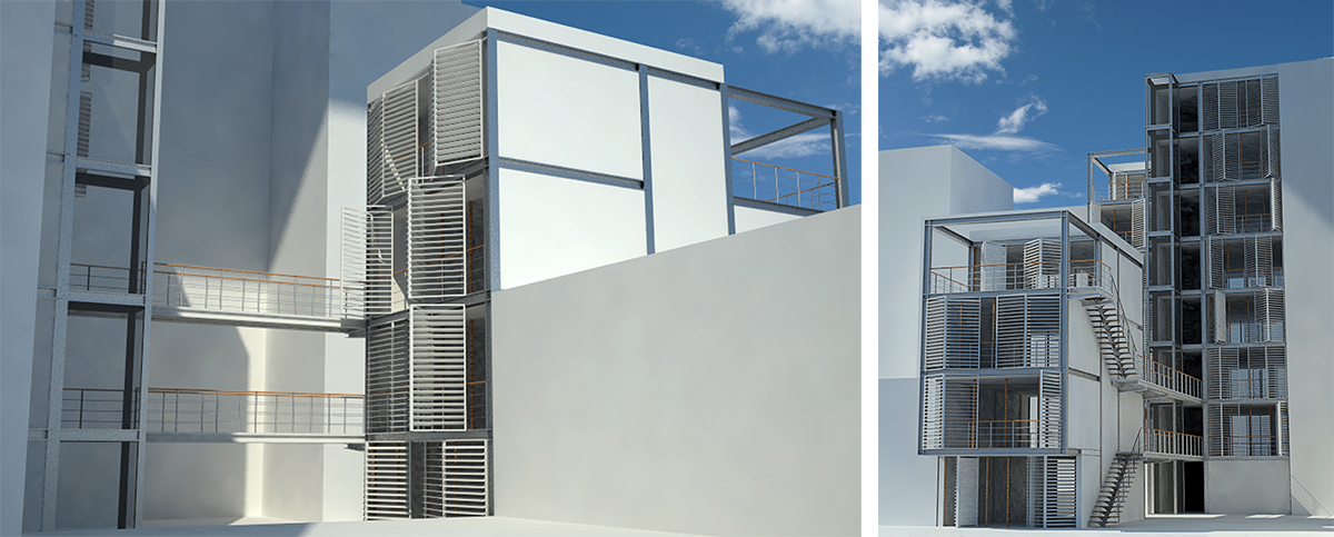
Détail de la structure
Housing project in Paris 19th


Projet de logement à Paris 19e
ENSA Paris Malaquais
Licence 2 semestre 2
Enseignant : Jean Léonard
Etudiant : Clément Gosselin
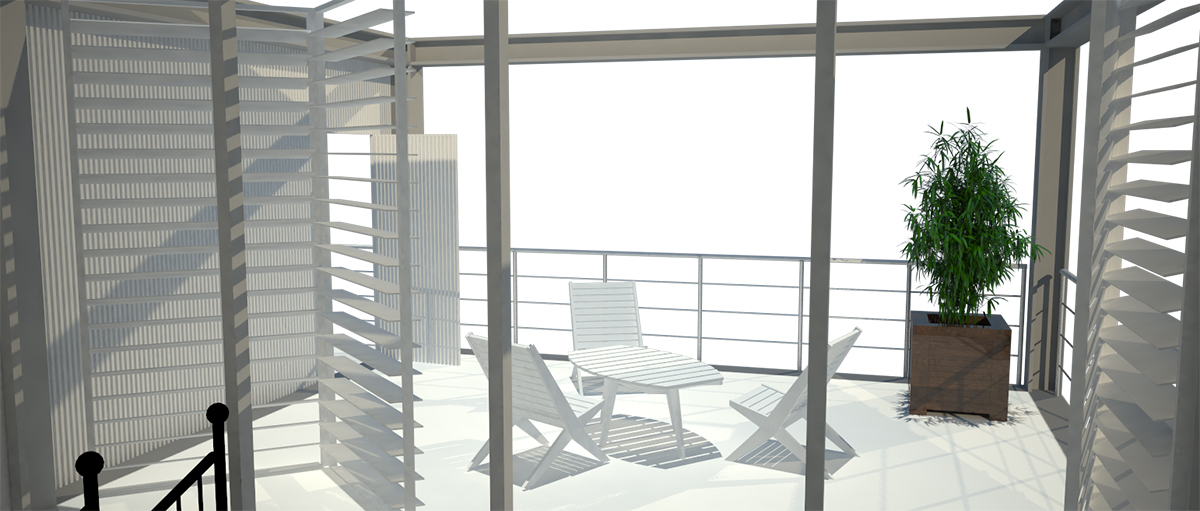
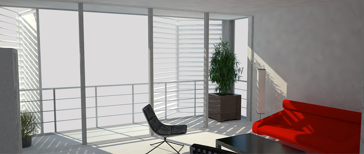
Il s'agit d'un projet d’immeuble en limite de Paris. L'ensemble du groupe de projet a participé à la conception du parcellaire sur l'îlot concerné, situé dans le secteur Ourcq Jaures. Les parcelles ont ensuite été distribuées à chacun de nous pour réaliser un projet comprenant un immeuble d'une dizaine de logement. Tout l’enjeu était de s’entendre avec ses voisins pour créer des continuités entre parcelles (alignements sur rue, cours communes...).
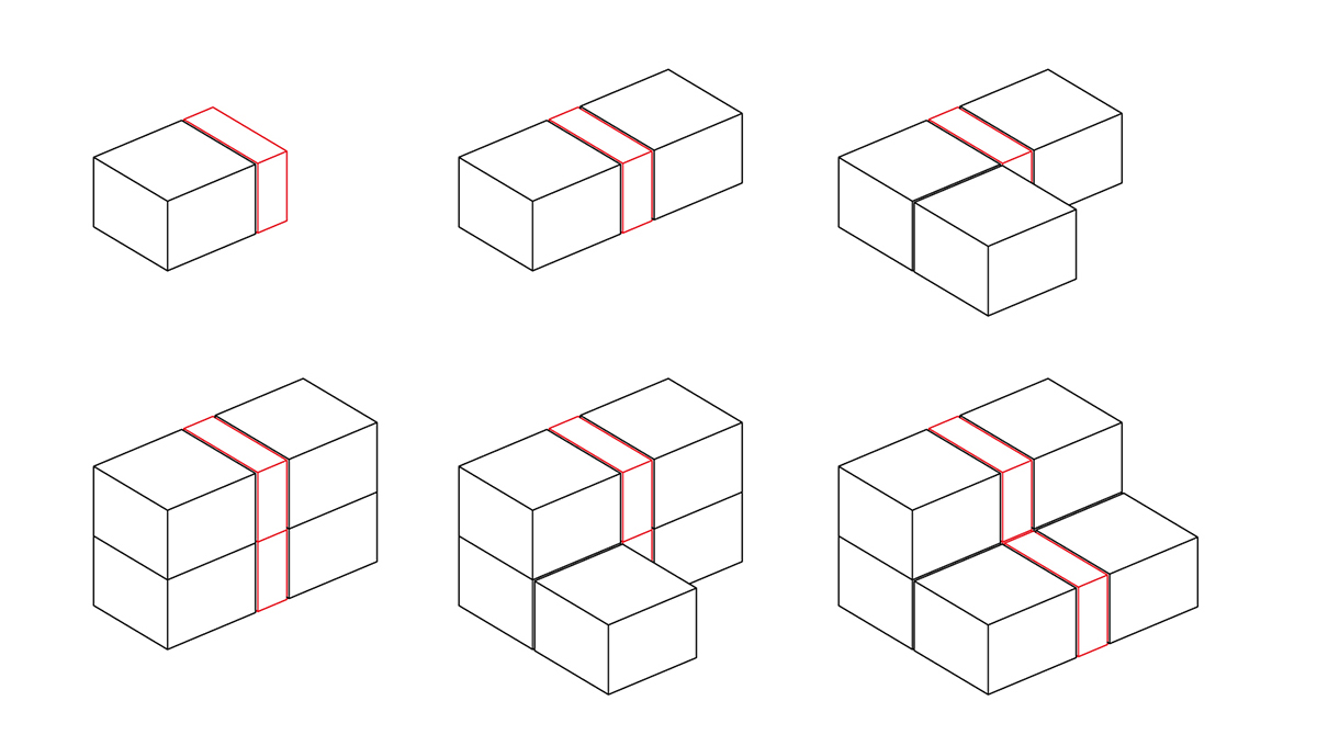
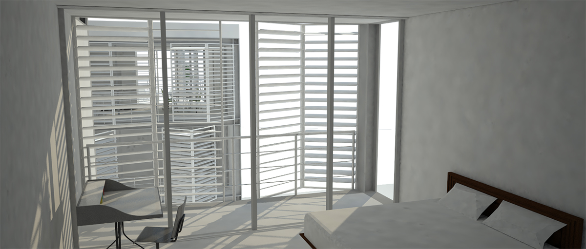
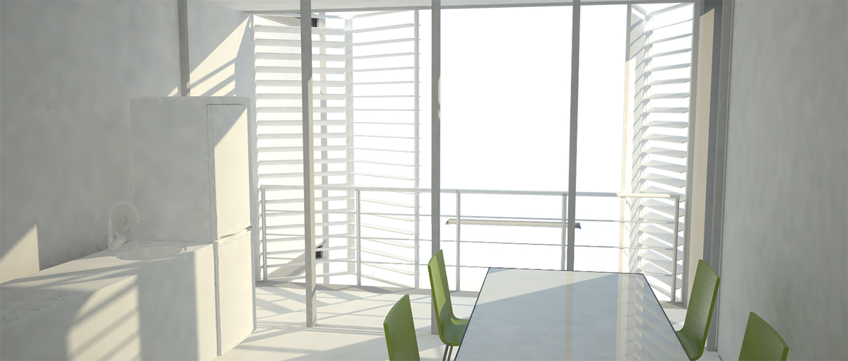
Concernant l'aménagement des logement, un système modulaire permettant une certaine flexibilité dans le plan, à la manière d'un plan neutre, fut conçus. Le système est composé de deux modules différents : le module spatial et le module technique. Chaque module technique dessert jusqu'à deux modules spatiaux. Le module technique contient tous les fluides (eau, électricité, fibre optique...), toutes les pièces nécessitant une évacuation verticale (toilettes) ainsi que toutes les circulations. Le module spatial permettant d’aménager les espaces. L’accès privilégié de ces pièces aux différents fluides permet de ne pas geler le plan : Les espaces peuvent s’interchanger (une chambre peut devenir une terrasse ou une cuisine).
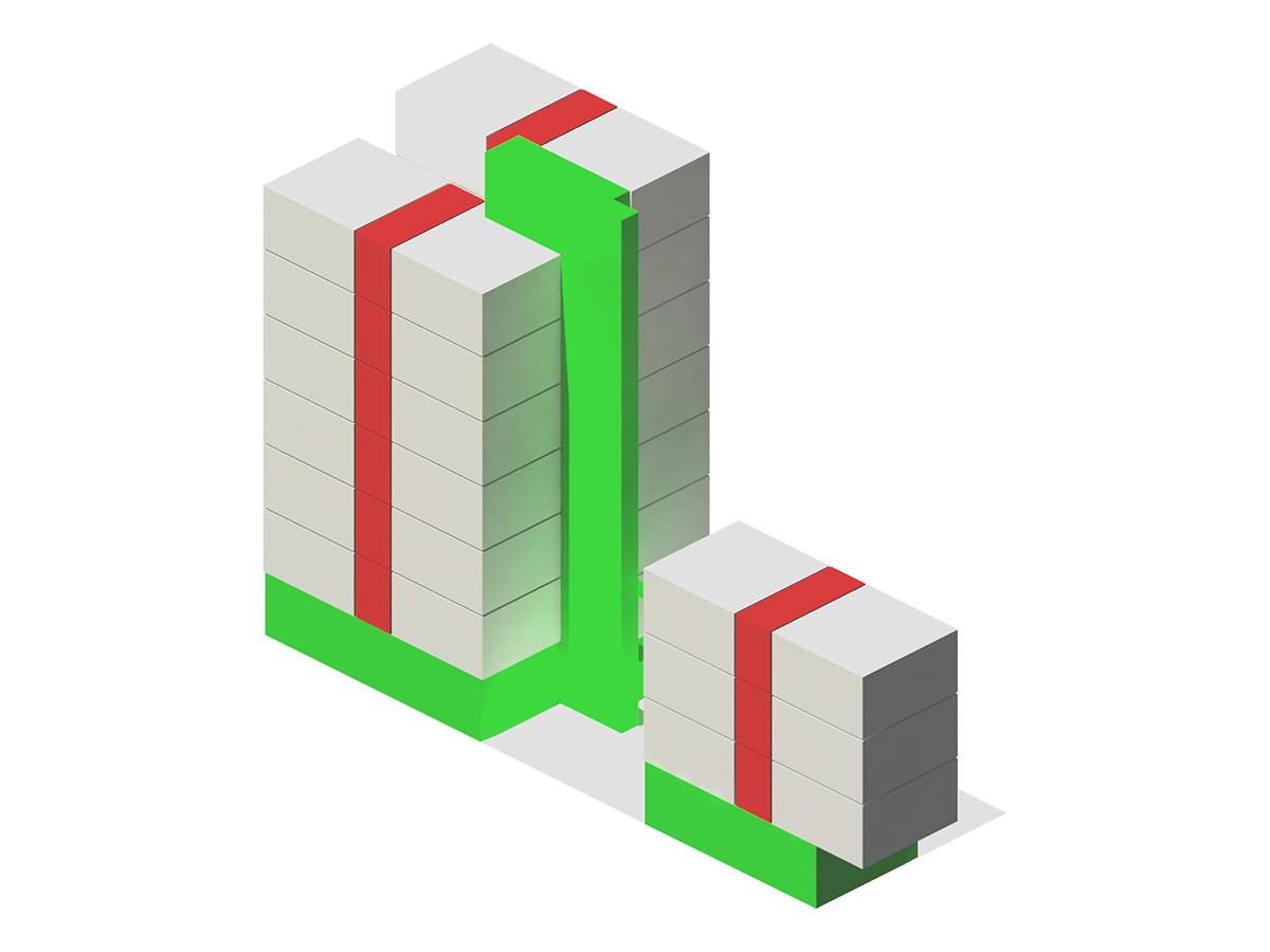
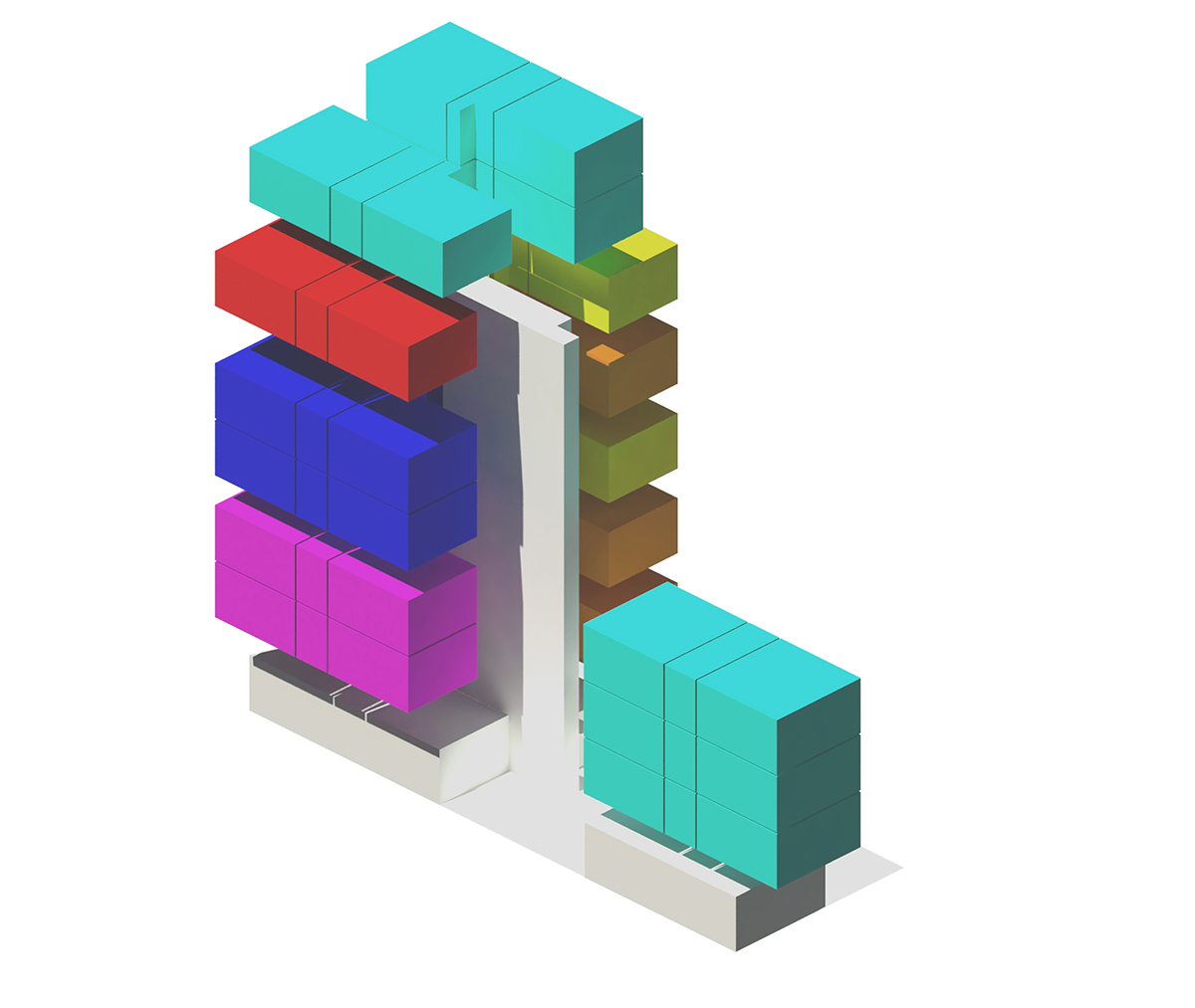
L'aménagement global de l'immeuble est le suivant : une seule circulation verticale dessert les deux corps de bâtiments. Les blocs techniques se correspondent d’un étage à l’autre formant des tours verticales où circulent les flux techniques principaux.
Le système modulaire mis en place permet de créer une grande variété d’appartements. Ainsi, l’immeuble possède des appartements comprenant entre un et six modules spatiaux : 2 appartements de 1 module, 3 appartements de 2 modules, 1 appartements de 3 modules, 1 appartements de 4 modules, 1 appartements de 5 modules, 2 appartements de 6 modules.
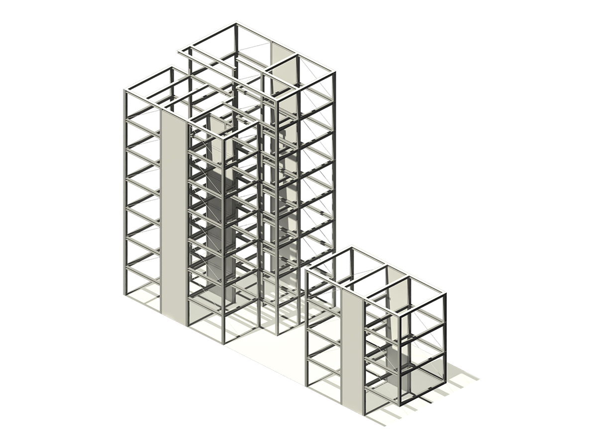
Concernant la structure, elle vise à libérer au maximum l’espace. Il s'agit d'un système poteau poutres en acier. Des portiques contreventement la structure dans le sens de la largeur de la parcelle. Le contreventement dans le sens de la longueur est assuré par des croix de Saint André situées dans les murs mitoyens. Les flux techniques (eau, eau usées, électricité, ventilation ...) passent également dans les murs mitoyens.
Helicoloidal stairs


Escalier Hélicoïdal
ENSA Paris Malaquais
Licence 2 semestre 1
Enseignant : Yulia Donestkaya
Etudiant : Armand Bultel, Corentin Héraud et Clément Gosselin.
Il s'agissait de réaliser une maquette au 1/10 d’un escalier hélicoïdale en béton armé. Pour ce faire nous avons modélisé sur ordinateur l'escalier ainsi que le coffrage à l'aide des logiciels Rhino et de son plug-in Grasshopper. L'intérêt de ce software est qu'il s'agit d'un logiciel paramétriques. Ainsi, nous somme parvenu à faire un scripte qui liait la géométrie de l’escalier avec un plan de découpe pour réaliser les éléments de coffrage. Nous pouvions ajuster la géométrie de l'escalier sans avoir à refaire le modèle du coffrage. L'épaisseur des éléments de coffrage était un paramètre du scripte. La modification de ce paramètre mettait à jour tous les plans de découpe.
L'escalier et la dalle ont été coulés séparément. Nous avons opté pour un escalier autoportant. D’où l’important ferraillage servant à maintenir le béton en place. Les marches en sous-face n’ont pas de rôle structurel. Elles permettaient de ne pas avoir à réaliser une surface réglée et facilitent donc le plan de coffrage. L’escalier a été coulé à l’envers et en premier. Il a ensuite été positionné pour permettre de couler la dalle.