ENSA Paris Malaquais
I worked for three years on an experimental research project about large scale additive manufacturing of cimentitious graded material from design to manufacture. I began to work on this subject during my first master term. It became gradually a team project. I led the research all along my master. During my final project I continued to work on this subject in the framework of a research project funded with the DEMOCRIT symposium with as partnership the ENSAPM, the ENSAM, the PIM, Hal Robotics and LafargeHolcime. This work led to several articles : Additive manufacturing and multi-objective optimization of graded polystyrene aggregate concrete structures , Design Modeling Symposium, Springer, 2015 and Large-scale 3D printing of ultra-high performance concrete – a new processing route for architects and builders Material and design 2016. The last one came out of the research project founded by the DEMOCRITE symposium.
Additive manufacturing technologies are today an important topic in the scientific field. Any kind of material can be printed (ceramic, metal, polymer, even organic cells). However, most of the technologies are made to manufacture small or medium scale object. Today there are no fully fonctionnal additive manufacturing technologies to build an architectural scale object. Few research about large scale additive manufacturing are being developed sine the end of the 20st century. The most interesting of them are D-shape and Contour Crafting. Since the first building prototypes were made in 2015 by the WinSun company in China lot of research program on this subject have been created.
Most of the researches on additive manufacturing are focused on fabrication technologies. There are even a few research investigations about developing large scale specific designing methods to generate advance geometry that takes into account the manufacturing constraints. Indeed, we can’t use computer aided drawing software to design 3D printed projects. We need to use computer aided design software to use all the potential of this manufacturing process. The material feature and the manufacturing constraints entail non-standard and complex shapes that can’t be drawn in computer aided drawing software. With computer aided design softwares we can create a project in relation with constraints by using the simulation tools.
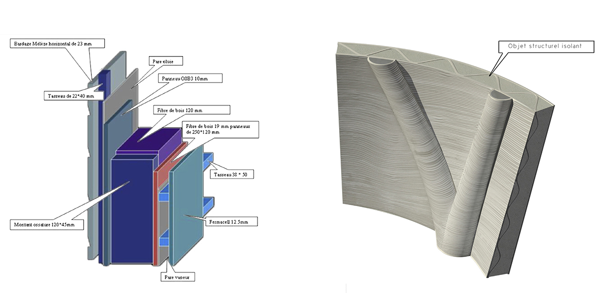
Additive manufacturing redefines the boundaries of the architectural elements. With this manufacturing process, there is no need to to divide the building in layers in relation to the specialist worker succession (structural wall, insolating material, facade). A synergy can be created between the different building organs that could create a new architectural element topology. Thus, this manufacturing process entails an integrative approach of the knowledge used during the design of the architectural project.
This work is about « design to manufacture » adapted to architectural scale additive manufacturing throughout a cross-disciplinary approach. The objective was to design, optimised and manufacture architectural element prototypes in relation to architectural design, technical performances and manufacturing process. Generate an optimised geometry for additive manufacturing is a complex work because the performances of a 3D printed object depend on 3 scale levels : the material properties, the tool-path deposition and the global morphology. Each one of them needs to be optimised in relation with the others.
I studied several aspects of this topic: the additive manufacturing process, the material formulation, the mechanical properties, the tool-path strategies and the morphology optimisation. I will now introduce briefly each one of those subjects.
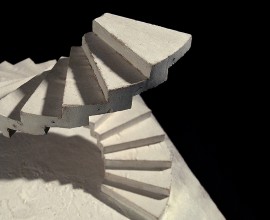
About the additive manufacturing process. There is for now no industrial operational turnkey solution. That is why I worked on a specific selective deposition manufacturing process. Indeed, that type of additive manufacturing process is more efficient for large scale object than selective solidification process. It was adapted to cementicious material. This process was thought to achieve graded performance material printing from structural to insolated material.
This process consists of two steps. First a mortar premix is prepared with reological behavior appropriate for pumping. At this stage the material has a small granulometry distribution, a low plastic yield value, a long setting time and be the less thixotrop as possible.
Then this premix is pumped to a printing head were several additives are added to the mixture to increase the plastic yield value, reduce the setting time and increase the thixotropie material properties. Otherwise, other specific additives can be added to change the material performance. In this work some tests were made with light aggregates (polystyrene beads) to change the material performance from structural to insulated material.
About the material formulation. I successively work with two different companies about the material formulation. I first worked with Chryso during the first three master’s terms (it was a non formal collaboration). Then, with Lafarge/Holcime in the framework of the research project funded with the DEMOCRIT symposium. For this research project LafargeHolcim developed a formulation adapted to additive manufacturing. The formulation derived from ultra high performance concrete (UHPC) (even if depending on the very small granulometry, this must be defined as a mortar). Therefore, it contains silica fume, a very low E/C (<0,1). Otherwise, it is optimised for the manufacturing process described above.. It has a long workability time and is composed of a specific polymer-base resin to reduce the structural interface issues between layers.
About the mechanical properties. Two specimens series were tested. The first serie was made with Chryso material for my master thesis. It was a compression test on cylindrical specimen. This test was made to compare poured mortar against printed mortar and also to determine the relation between the the tool-path and the material performance and fracture feature. The compressive resistance of printed specimen is roughly 40% less important than the poured specimen one and the fracture failure is directly linked to the tool-path. Printed mortar has a pseudo ductile failure method (it is not brittle as the poured mortar). The second test serie was made with lafargeholcime material. It was a flexion test to compare poured mortar against printed mortar. There was only 10% difference between the structural performances of the two groups of samples .
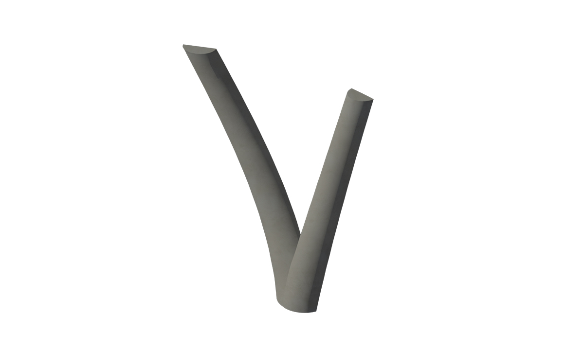
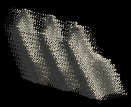
About the tool-path strategies. The classical slicer software we can use for polymer 3D printing are not adapted to large scale objects. Indeed, those slicing methods consist of planar layers constituted of one or several boundary laces and a filling lace pattern. Otherwise, because we are dealing with planar layers the objects produce with this method can be compared to corbel structures, which is one of the less efficient structure typology because it make the laces work with flexion and, in some case, the interfaces work with traction. To create a tool-path method adapted to large scale object we have to orient the laces in the three dimensions. This can be done by using the layering anisotropy to optimise the behavior of printed structure. The layer interfaces are the week structural point. The best orientation for those interfaces is to constrain them in compression. However the laces work fine with traction, especially if we are dealing with a fiber-reinforced mateial. To design an object that takes into account those constraints, we needed to generate a 3D tool-path which is totally different than classical planar layering methods.
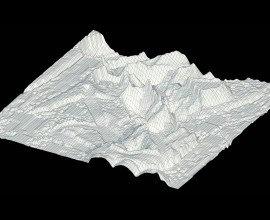
About the morphology optimisations. I worked with two engineers on a GA-based multi objective optimisation algorithm. It was designed to optimised the repartition of several materials depending on their properties. Basically, we were working on an algorithm that can optimise the distribution of structural and insulated material depending on the specific boundary constraint (thermal and load constraints). This algorithm was not taking additive manufacturing constraints into account.
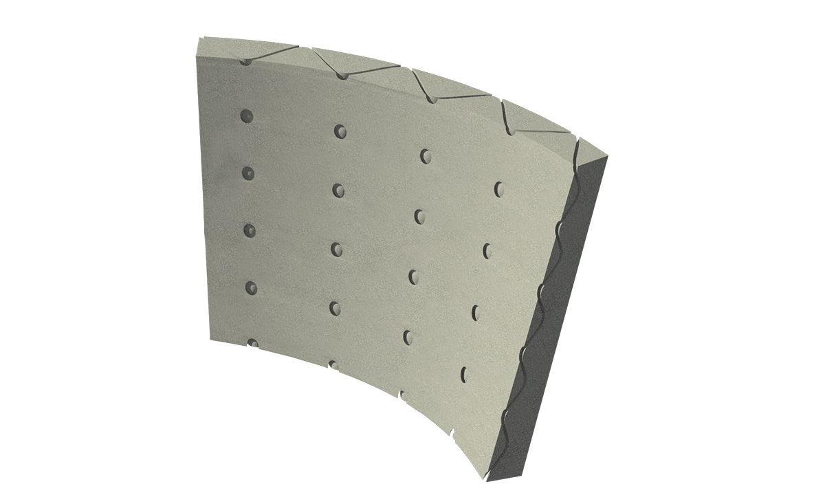
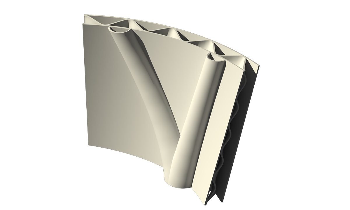
During my last term project, we chose to work on a case study of a reconstruction project where the existing structure is extremely damaged. The reason of this choice was to work with a contrained environment. Indeed, that kind of existing environment is a huge constraint that requires complex non-standard architectural éléments. The idea was to design a project made to be built with large scale additive manufacturing of cementitious material and produces a scale 1:1 architectural element. This design project took into account all the research introduced above about the manufacturing process, the material formulation, the mechanical properties, the tool-path 3D strategies and the morphology optimisation.
The architectural element produce was a loosed formwork. It is constituted of two parts : one made to receive poured structural mortar and one made to received poured insulated mortar. The structural part is designed in relation to a specific load. The insulated part is designed to reduce thermal bridges. The tool-path is generated to orient the lace interfaces perpendicular to the compression stress.